From Dev Board to Volume: An OEM Checklist for the 0.39-Inch 1024x768 Micro OLED VR Headset Display
The distance between a 0.39-inch Micro OLED module that works on a dev board and one that ships inside a VR headset is measured in drawings, fixtures and test limits rather than in pixels. A 1024x768 emissive panel on an RGB/SPI interface is straightforward to bring up and genuinely difficult to keep consistent across a production run, because the variables that matter - flex routing, connector seating, grey-level behaviour, heat next to the user's face - only appear once the module is assembled into the product. The practical conclusion is to treat customisation and tooling as design work that starts before the enclosure is frozen, not as purchasing steps that happen afterwards. What follows is written for the engineer who has to sign the handover from prototype to volume.
Key takeaways
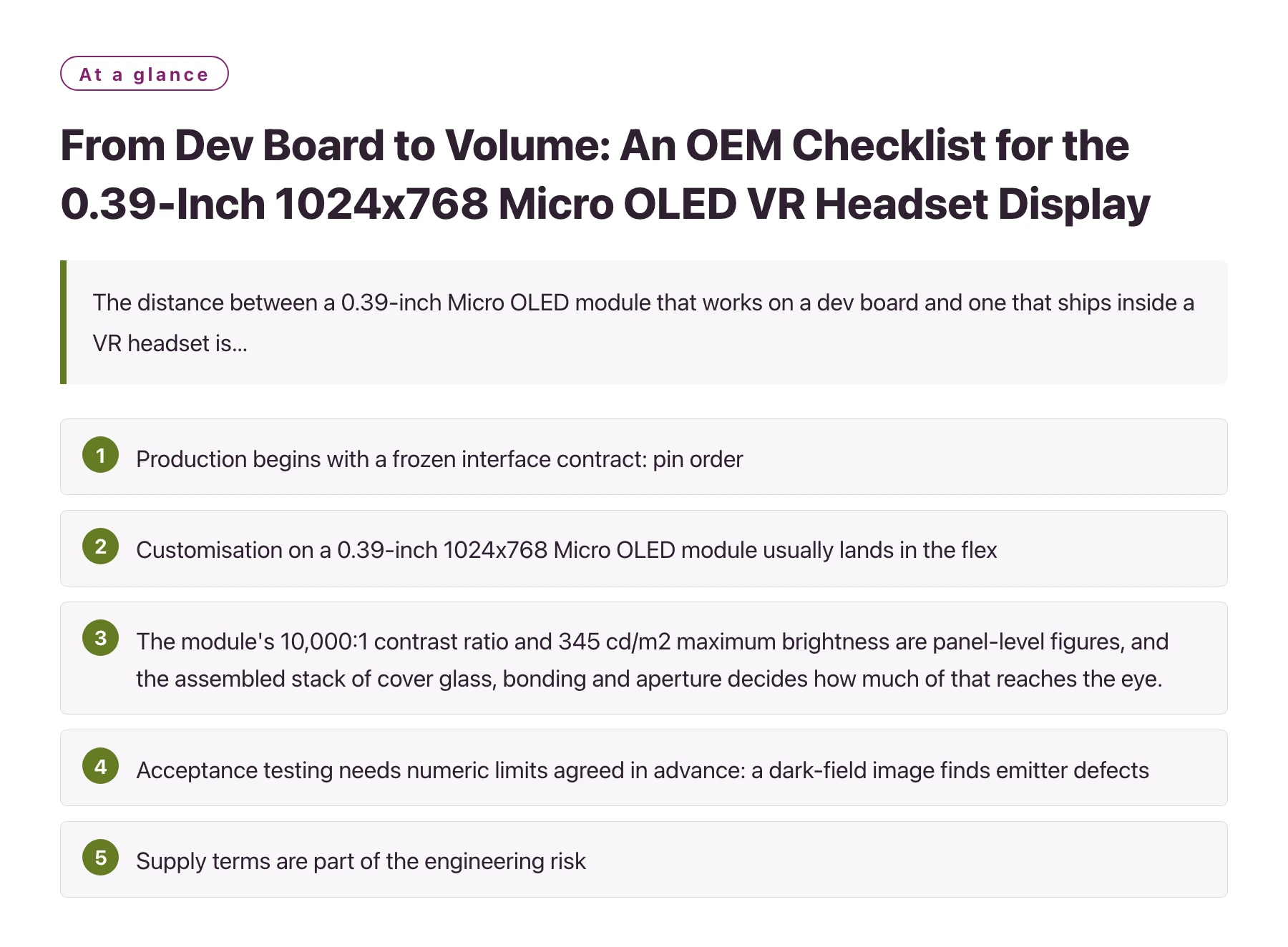
- Production begins with a frozen interface contract: pin order, clock polarity and phase, chip-select behaviour and the power-up sequence for the RGB/SPI link belong in a controlled document, because SPI is a full-duplex synchronous serial bus whose timing is only as good as the clock and the wiring that carry it. [1]
- Customisation on a 0.39-inch 1024x768 Micro OLED module usually lands in the flex, the mounting frame and the cover rather than in the panel itself, so tooling spend concentrates in mechanical parts and test fixtures.
- The module's 10,000:1 contrast ratio and 345 cd/m2 maximum brightness are panel-level figures, and the assembled stack of cover glass, bonding and aperture decides how much of that reaches the eye.
- Acceptance testing needs numeric limits agreed in advance: a dark-field image finds emitter defects, a stepped grey ramp exposes gamma and uniformity drift, and a supply-current check catches flex or connector damage that a pleasant test picture hides.
- Supply terms are part of the engineering risk, since minimum order quantity, lead time, life-of-product notice and the change-notification process decide whether a panel revision can quietly invalidate your optics and your calibration.
Micro OLED is an emissive technology, meaning each pixel generates its own light and a black pixel emits nothing at all, so there is no backlight to leak through the dark state. That is a large part of why this panel class suits near-eye products. It is also why the mechanical stack in front of the panel is unusually visible in the final image, because every added surface reflects ambient light back into an optical path the user's eye sits only centimetres away from. [2]
The module in question is a 0.39-inch 1024x768 Micro OLED panel with an RGB/SPI interface, specified at a 10,000:1 contrast ratio and a maximum brightness of 345 cd/m2, and positioned for AR/VR, medical imaging and industrial equipment. In a VR headset it is one image source in a binocular pair, so it is bought as a pair even when the design work starts with a single unit on the bench. Volume production turns that pair into a matched set that has to track the other half in brightness, colour and geometry.
This article follows the module from breakout-board bring-up to a production line: what actually gets customised, where tooling cost sits, which tests earn their place, and which questions should be answered by the supplier in writing before a mould is cut. Where a decision depends on a manufacturer's process, the text says so rather than assuming a number. The engineering content stands on its own whether or not you end up buying this particular part.
Why a dev-board proof does not define production
A proof build has one job: show that the panel, its driver and the host can talk to each other. An off-the-shelf microcontroller board with a short jumper harness accomplishes that, and the result is usually reported as a working display. Nothing in that setup describes a product, because harness length, connector type, supply impedance and thermal path are all arbitrary. The proof is a green light for the interface, not for the design.
The RGB/SPI link is where that ambiguity accumulates first. Because the bus is clocked by the host and travels over the same flex that carries power, the display's timing is only as stable as the host clock tree and the return path underneath it. Change the flex length, add a board-to-board connector, or route the clock beside a switching regulator, and edges that looked clean on a bench jumper begin to fail on a fraction of assembled units.
The interface description has to be a controlled document
Pin order, clock polarity and phase, chip-select behaviour, reset timing and the order in which the panel rails come up relative to the first frame should live in a document that the supplier and your firmware team both sign. The practical test of that document is whether a new engineer can wire a fresh board from it alone, without asking a colleague or reading one person's private header file. If the answer is no, the document is not finished, and every future handover will restart the same bring-up.
Keep the timing tables in the same document as the connector pinout. Splitting interface timing into firmware comments and keeping the mechanical details in a drawing set guarantees that the two drift apart the first time either is revised.
Mechanical truth arrives before electrical truth
In a headset the panel is normally mounted in a frame that also carries the lens and the cover, and the flex has to follow a defined bend. Bend radius, bend direction and any strain relief are specified by the flex supplier rather than chosen by the assembler at the bench. Obtaining a drawing of the recommended bend region together with the flex quotation is the cheapest way to avoid a redesign later.
Ask for the tolerance stack at the same time. The gap between the panel's visible area and the frame aperture is what a user perceives as an uneven border, and an aperture that is generous enough to absorb assembly variation is usually cheaper than tightening every part in the chain.
The useful question at this stage is not whether the prototype works, but which of its properties you can restate as a specification.
Six prototype habits that turn into volume problems
| Decision | Enough on the bench | What volume exposes | Who owns the fix |
|---|---|---|---|
| Host clock and SPI timing | Jumper wires and default clock divider on one board | Flex length and connector seating vary per unit, so a marginal timing setup fails on a subset of builds | Firmware and electrical |
| Flex and connector | Hand-soldered or socketed link, bent by hand during bring-up | Repeated bending at a hinge relaxes the FPC and stresses plating, and insertion force varies by connector lot | Mechanical and supplier |
| Optical stack | Bare panel, or a quick acrylic window held in front | Cover glass and bonding adhesive add internal reflections and can lift the black level that the contrast figure depends on | Optics and process |
| Brightness and grey levels | One white screen judged by eye | Low-grey uniformity and white point shift with drive current and temperature inside a sealed enclosure | Firmware and quality |
| Acceptance criteria | Watch a test image and decide whether it looks right | Without a numeric limit, the first returned unit cannot be classified as pass or fail | Quality and supplier |
| Documentation | Firmware header file maintained by one engineer | Every handover restarts bring-up, and supplier changes cannot be assessed against a baseline | Programme engineering |
A sequencing order that keeps tooling cost predictable
- Freeze the mechanical envelope first. Anchor the panel position to the lens axis and the eye relief, then let the flex and the frame follow. Changing the frame after the flex tool is cut means paying for both parts twice.
- Quote flex, frame and fixture as separate lines. A single lump-sum quotation hides which item carries the tooling cost and which one can be revised cheaply, and it also obscures where a second source is realistic.
- Write the acceptance test as numbers. Specify the test pattern, the instrument, the measurement point and the pass band for brightness uniformity, dark-field defects and supply current before the pilot lot is built, not after it fails.
- Run the pilot on the real line. Assemble at least one lot with production operators, production fixtures and production adhesive. Hand-built pilot units answer electrical questions and conceal process ones.
- Agree the change-notification channel. Ask how you will hear about a panel, driver or flex revision, how much notice you receive, and what sample or data comes with it. A verbal assurance from a sales contact is not a process.
Test points that catch what a pretty picture hides
An emissive panel has no backlight to fail, which removes one class of problem and leaves the ones that are harder to see. Dark-field inspection at a black image finds stuck-on emitters, particles trapped under the cover and bonding voids, because anything that leaks light stands out against a true black. A stepped grey ramp does the opposite job: it reveals gamma error, banding and low-grey uniformity problems that a saturated test image will conceal.
Contrast ratio is defined as the ratio between the luminance of the brightest state and the luminance of the darkest state, measured under stated conditions, which is exactly why the figure depends on the measurement setup as much as on the panel. [3] A module specified at 10,000:1 can still appear washed out in a finished headset if the cover glass reflects room light or the bonding layer scatters. Measure contrast in the assembled stack, not only on a bare panel, and record the ambient conditions alongside the result.
Supply current belongs in the test record for an unglamorous reason: a partly cracked flex or a poorly seated connector frequently draws measurably more or less current before it produces any visible defect. Capturing that number per unit converts a future field failure into a trend that is already visible in the data.
Thermal soak inside the product enclosure
Operating temperature ratings describe the range over which a device is specified to function, and the panel, the driver and the finished module can each carry a different one. [4] Ask the supplier which component holds which rating, then measure the enclosure yourself with the headset running its worst-case workload. A short bench run at room temperature says very little about a sealed unit held against a warm face.
What to retain from every unit
Serial number, test results, current draw, the fixture used and the production shift are the minimum traceability set for a display module. It is also worth keeping one photographed dark-field image per lot, because a picture of a defect is far easier to discuss with a supplier than a description of one.
If a test cannot distinguish a good unit from a marginal one, it is a production step rather than a quality gate.
A panel change is not a drop-in event. Even when a replacement carries the same resolution and interface, the driver configuration, the gamma tables, the flex footprint and the mechanical envelope can all move, so the acceptance test has to be re-run rather than inherited. Budget one full qualification cycle for any panel or driver substitution, and treat the supplier's notice period as a schedule input rather than a formality.
Customisation, cost and the OEM conversation
What most buyers actually customise on a small Micro OLED module is the package around the glass: the flex length and shape, the connector type, the mounting frame, the cover glass and its coating, and the test fixture. Panel-level changes depend on the substrate process and belong to a much longer conversation. Knowing which side of that line a request falls on is what decides whether a change costs weeks or a programme.
The 0.39-inch 1024x768 Micro OLED module family represented by DisplayModule displays is a sensible starting point for a VR headset programme precisely because the electrical interface is conventional, which leaves the customisation budget for the flex, the frame and the optics instead of a new silicon design. The same panel class also appears in medical imaging and industrial equipment, so a supplier that already builds it for several markets is more likely to have an inspection and test flow you can inherit rather than invent.
Bring four items to the first OEM/ODM meeting: projected annual volume, the mechanical envelope, the acceptance test you intend to enforce, and the date the optics have to be frozen. A supplier conversation without volume and envelope turns into a general catalogue discussion, and the answers that come back will be generic for that reason. Ask separately about minimum order quantity, lead time on a repeat order, and how the module is packed and shipped, because those three determine how much buffer stock a programme has to carry.
Request the documentation set early as well: outline drawing, flex drawing with its bend specification, interface timing tables and the material declarations your compliance team will need. Documents requested after tooling is cut are documents negotiated from a weaker position, and the schedule pressure at that point rarely improves the terms.
Sources
Frequently asked questions
What does OEM/ODM customisation realistically cover for a 0.39-inch Micro OLED module?
It typically covers the flex, the connector, the mounting frame, the cover glass and its coating, the test fixture and the packing, while the 1024x768 emissive panel and its driver remain a standard part. A panel-level change is a different project with a different timeline, because it depends on the substrate process rather than on module assembly. Asking which category a request falls into is the fastest way to estimate whether it costs weeks or a full programme.
Should a VR headset run this module at its 345 cd/m2 maximum brightness?
Not by default. The maximum brightness figure describes what the panel can deliver, and the assembled stack in front of it reduces what actually reaches the eye, so the useful design target is the luminance measured at the exit pupil rather than the panel figure. Higher drive current also means more heat inside a sealed enclosure held against the user's face, which affects comfort and the grey-level behaviour you calibrated. Measure at the eye position and set brightness from that measurement.
How do I write an acceptance test for an emissive display with no backlight?
Use the emissive behaviour to your advantage: a black field exposes stuck-on emitters, trapped particles and bonding voids, while a stepped grey ramp reveals gamma and uniformity errors that a saturated image conceals. Add a supply-current measurement with a numeric band, because a damaged flex or a poorly seated connector usually shifts current before it changes the picture. Then fix the fixture, the instrument and the ambient conditions in the test document, since a pass band is only meaningful alongside the setup that produced it.
What belongs in a change-notification agreement with a display supplier?
At minimum: which changes trigger a notice, how far in advance it arrives, what sample or data accompanies it, and who on your side receives it. Panel, driver, flex and adhesive revisions all belong on that list, because each can move either the gamma behaviour or the mechanical envelope. Without a written process, the first time you learn about a change may be when a production lot fails an optical check.